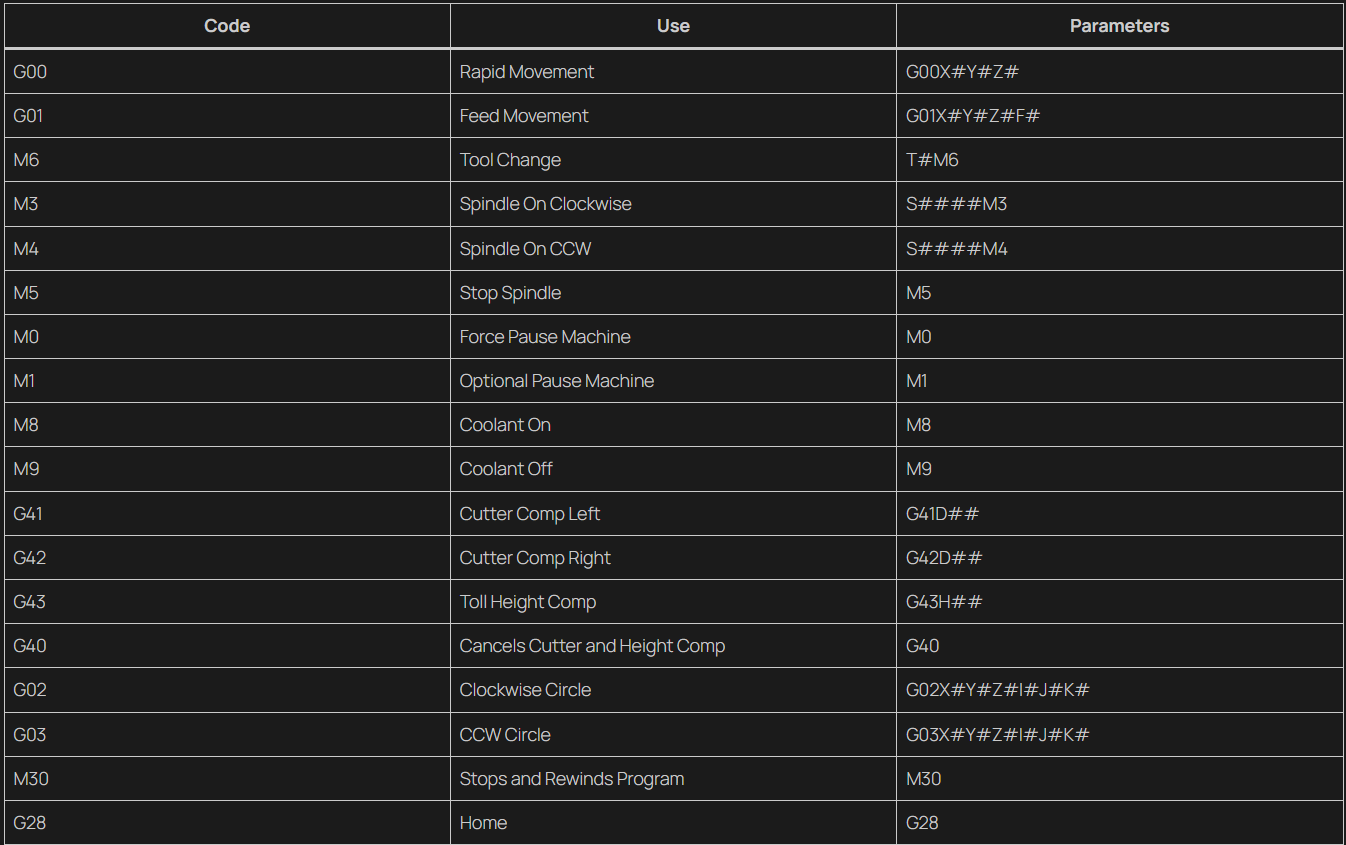
CNC Hand programming is handwriting programs. While as a fact no-one handwrites programs anymore, for beginners looking for in depth knowledge this is an extremely useful skillset.
Vertical Mill Hand Programming.
G and M Codes: Numerical Control
To start, with some of the simplest and most basic codes, we have G01 and G00.
G00
G00 is for Bulk and Fast movement, do not use this for cutting. It is solely intended to move quickly from your current position closer to your material. Typically you will move to your X0.0 and Y0.0 then to a few inches above the part.
Task: Move your tool to one inch above your part.
Example:
(X0.0Y0.0 Center of Material)
(Z0.0 Top of the Material)

G00X0.0Y0.0; (moves to center of the part)
G00Z1.0; (Moves to one inch above your part)
G01
G01 is for cutting, you need a feed rate that is typically in Inches Per Minute (IPM). The Program will not run without a feedrate(F__).
Task: From your previous position, move to the bottom left corner, one inch away in the X and Y. Then move down and cut 0.020″ deep up to the top left corner one inch away in the X and Y. Use a Feedrate of Five Inches Per Minute.
Example:

G01X-1.0Y-1.0F5.0; (Moves to bottom left corner)
Z-0.010; (The Program will stay in G01 and reuse the feedrate of 5.0IPM)
X-1.0Y1.0; (Moves directly up and travels two inches)
As you can see here, the machine will remember the last G00 or G01 used. You do not need to write it each time, you can simply write it once then input the rest of your coordinates. Ensure that you are in the correct Cutting(G01) or Rapid(G00) mode otherwise you can break a tool, damage the part or crash the machine.
Comments (I am a comment)
At the beginning, at tool changed, the beginning of blocks and occasionally in the middle, there will very often be Comments in parentheses. The program will ignore anything within the parentheses.
(Zero is on top of block)
(XY is in the top left corner)
(Use tool 5, .125R 3/4 End Mill)
These lines provide useful information, the program will ignore them but the operator can see them at the machine.
M3 and M4
M3 will turn on your spindle Clockwise, M4 will turn your spindle on CounterClockWise. You will almost always use M3, nearly every CNC Machine tool is designed to turn Clockwise. S____ will set the speed in Rotations Per Minute (RPM). Be very careful that you did not mistype the speed value or it can severely damage something.
Task: Turn the Spindle to 2500 RPM.
S2500M3; (Sets the spindle speed to 2500RPM, Then turns the spindle on Clockwise)
Work Offsets: G54
Your work offset tells the Machine where your workpiece is. There is a separate Article about how to set your work offset here (LINK). For now we will assume it is already set.
For Mills, your Work Offset can be any number between G54-G59. It will include three numbers, your X, Y and Z values. Ensure these are set correctly, otherwise you can scrap a part or crash the machine.
Task: Call your work offset.
Example:
G54; (Sets your work offset to G54)

(It is that simple, just don't forget it)
Height Offsets: G43 and Height
Another set of Data you need to pay attention to is your Tool Height. All of your tools are different lengths, they can wear down, and when you replace them it’s nearly impossible to get them in the exact same place.
G43 is the code to turn on height offset compensation. If you include a height offset value without it, the code will do nothing. Then you could scrap a part or crash the machine.
There is another Article on how to set your height. Your Height will be stored in your Tool Offsets, under the H#. # is whatever tool you are using. T5 is H5, when setting up, it is very common when setting up a machine to leave a tool in it’s existing position. When you do so make sure you change your Height Value as well.
Task: Set your height value to H2
Example:
G43H2;
Tool Changes: M6
In order to run a program effectively you may need multiple tools, in order to toolchange, you use the code M6.
Task: Switch to tool 19.
Example:
T19M6; (Calls up T19 then switches tools with M6.)
Remember to turn the spindle back on before cutting! M3S____
Exercise Section:
Create a program, that switches to T5, a half inch endmill. Then cuts a 1 inch square in the center of a 2 inch block using a spindle speed of 2,000 RPM and a Feedrate of 5IPM.
Answer
O4001;
G90 G80 G40 G20 G17; (Safety line, explained in the next section)
T5M6; (Selects Tool 5 and switches using M6)
G43H5; (Enables Length based compensation with G43 and Selects Height 5)
G54: (Selects work offset G54)
(Rapid Moves)
G00X0.0Y0.0;(Moves to X0Y0)
Z1.0;(One inch about the Part)
<INCOMPLETE>
Radial offsets: G41 and G42
Often, your tool will not be the exact right size for the task. It may be 0.001″ too big or “-0.003 too small. We can compensate for this using G41 and G42, this is often handled by the CAM Software, but here we will do this manually.
The Offset D number will have two numbers a Diameter which is typically set to 0.000, and a Wear offset. The Wear offset is used to make small adjustments. You can program you toolpath to match a specific tool, such as a 1/4″, 3/8″ or 1/2″, or more rarely you can program the toolpath to follow the edge of your part. Then set the Diameter to the size of your tool. This is uncommon and will typically only be done when learning. We will do it in the next exercise.
G41: Offsets the Tool to the Left of the Toolpath.
G42: Offsets the Tool to the Right of the Toolpath.
If your tool is travelling on the near side of a block, left to right. You would use G42, this offsets the tool to the Right, which will compensate for your wear or tool size. If travelling from right to left, you would use G41. This offsets the tool to the left of the tool path.
Task: Draw a 1 inch square Offset clockwise, then the same square Offset counter-clockwise.
Canned Cycles
Canned Cycles are prepackaged functions that are useful to simplify programs and improve readability. The most common ones are for drilling, listed here:
G81 Straight Drill Cycle
G82 Spot Drill Cycle
G83 Peck Drill Cycle
G80 Cancel Canned Cycle.
Every Canned Cycle will start with a G8_ Code and end with a G80 code in a self contained block. If you do not include a G80 at the end, the program will interpret any additional coordinates as additional places to drill. This could result in a undesirable amount of holes in your work piece.
Example:
G01 X1.0Y1.0F5.0; (Feed towards first hole)
G83 X1.0Y1.0R0.1Z-1.0Q.200F2.0; (At X1.0Y1.0, a Peck drilling cycle is initiated with a Retard of R0.1 a peck depth of Q0.200 and a Feedrate of F2.0)
X1.0Y2.0; (Drills a second hole at X1.0 and Y2.0)
G80; (Cancels Canned Cycle)
Feeds and Speeds
Exercise, Facing program
Exercise 123 Block
Lathe Hand Programming
G00
G00 works exactly the same way as on a mill, but in the X and Z Axis. It is Best Practice and often necessary to move each Axis in a specific order, otherwise you could crash the machine. When approaching a work piece, you should almost always approach with the Z First then the X. If you move the X fire you can crash into the Tail Stock.
When returning to home, you should always make sure you are clear of the part, home the X(G28U0.0) first and then the Z(G28W0.0). This is done for the same reason as approaching the part, if you do not you can crash into the tail stock. If you are using a Drill, ID(Internal Diameter) Threader or Boring bar make sure you retract it First before sending X Home.
G01 and G00
Work offset
Tools
Tool Changes
Constant Surface Speed
G50
Arcs