Section 1: Basic Circuit Analysis Groundwork
| Name | Symbol | Use | Units |
|---|---|---|---|
| Amp | A | Current Flow | A |
| Columb | C | Electric Charge | A · s |
| Volt | V | Electric Potential | kg · m² · s⁻³ · A⁻¹ |
| Ohm | Ω | Resistance | kg · m² · s⁻³ · A⁻² |
| Watt | W | Power | kg · m² · s⁻³ |
| Joule | J | Energy | kg · m² · s⁻² |
| Farad | F | Capacitance | kg⁻¹ · m⁻² · s⁴ · A² |
| Henry | H | Inductance | kg · m² · s⁻² · A⁻² |
| Hertz | Hz | Frequency | s⁻¹ |
Basic Equations
The Fundamental Equations we will use often throughout this course are.
V=IR is the simplest and most fundamental equation. Memorize it, we will be using it alot. Voltage(V) is Equal to Current(I) Multiplied by Resistance(R). You can rearrange this equation as needed. To solve for Current and Resistance.
Example:
Section 2: Parallel and Series Calculations
The equation for Parallel Resistance is
The Equation for Series Resistance is
Exercise 1:
Section 3: KVL and KCL
Kirchhoff’s Voltage Law: All voltages in a Loop must add up to Zero. This means that when you add the Voltage Source to the Voltage drop of the Resistors, the total voltage will equal 0.
This is best shown with a example.
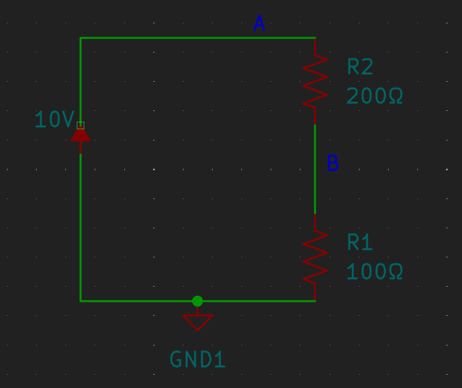
The Voltage source provides 10 Volts, the Resistors R1 and R2 provide a Voltage drop that together will equal 10 Volts. To calculate this we need one additional equation and concept.
Voltage Drop
A necessary component of using KVL Effectively is Voltage Drop. Given two Resistors in Series, the Voltage drop across each of them will be proportional to the resistance. As a example, a 12v source, that runs through two resistors R1=1ohm and R2=2ohm. The Voltage Drop will be equal to.
This is true for any number of resistors in Series. The denominator represents Total Resistance in Series.
Using this equation and the previous example we can solve for the Current in R1.
Using the same Method for R2.
Remember, this is a voltage drop, when we sum the Currents in this equation 10VSource -3.33VR1-6.67VR2 = 0 we can see that Kirchhoff’s Voltage law is true. !!!!!
Kirchhoff’s Current Law: All Currents entering a node must add up to Zero
EXAMPLE IMAGE
Exercise 1: Solve for the Voltage in the Resistor R2
Exercise 2: Solve for the Current in Resistor R2
Section 4: Power Equations
You can solve many equations using Conservation of Energy. Fundamentally this involved Power equations, the sum of all the power entering or leaving the system must be Zero.
The fundamental equations are.
Power is Equal to Current(I) times Voltage(V)
Power is equal to Current(I) Squared times Resistance
Power is equal to Voltage(V) Squared times Resistance
Exercise 1:
Section 5: Mesh Voltage and Node Current Methods
Two methods, that fundamentally are extensions of KVL/KCL are the Mesh Voltage and Node Current Methods. I will describe them together, then go into them separately. The Mesh Voltage and Node Current Methods, involve getting a series of Linear Equations, then solving them simultaneously. You can solve these linear equations manually, but i highly suggest using a calculator for this.
Mesh Voltage
Mesh Voltage fundamentally relies on Kirchoff’s Voltage Law, the Voltage in a Loop must equal Zero.
Node Current
Section 6: Source Conversion and Voltage Dividers
When evaluating a circuit, it may be convenient or necessary to convert between a voltage source and a Current source.
Section 7: Op Amps
Previously, before Digital Electronics Opamps were used to do analog Math operations.
Op Amps have a couple features and properties that make them very useful. Understanding these features and properties makes solving simple circuits with them extremely straight forward.
The Op Amp will try to make the Voltage of both Inputs equal. A Ideal Op Amp will not allow any current to pass through either input. The Voltage provided by the Output cannot exceed the Supply(+/-).
Features and Equations.
- Input(+)
Non-Inverting Input, Vin+
Must Equal Vin-
Vin- = Vin+ - Input(-)
Inverting Input, Vin-
Must Equal Vin+
Vin+ = Vin- - Vout
Output
Vout =A(Vin+ – Vin-) - Supply(+)
Provides power to the Op Amp
Vout Cannot exceed Supply(+) - Supply(-)
Provides power to the Op Amp
Vout Cannot exceed Supply(-)
Amplitude
Integrator Circuit
Sumer Circuit
Example 1:
Section 8: Applications of Calculus and Inductors/Capacitors
Capacitors and Inductors store energy in various ways. Capacitors store energy in Electric Potential, Inductors store Energy in a magnetic field. In DC circuits, when you apply a voltage and current to one of them, they eventually become Saturated.
The Natural Response, is when a Saturated Capacitor or Inductor is suddenly disconnected from the power source. What they do following that is called the Natural response, which is defined by First Order Differential Equations.
“n” here means for any quantity of resistors, capacitors or inductors that are all in either series of parallel.
| Component: | Resistance | Capacitance | Inductance |
|---|---|---|---|
| Series: | R1+R2+Rn=R | 1/C1+1/C2+1/Cn=1/C | L1+L2+Ln=L |
| Parallel: | 1/R1+1/R2+1/Rn=1/R | C1+C2+Cn=C | 1/L1+1/L2+1/Cn=1/L |
| Equation | R=V/I | C=i(t)/(dv/dt) | L=v(t)/(di/dt) |
Types of circuits RLC, RL, RC circuits
Natural response vs step response
There are various current equations for a Resistor, Inductor and Capacitor.
There are various voltage equations for a Resistor, Inductor and Capacitor.
RL First Order Differential Equation
RC First Order Differential Equation
RL Power Equation
RC Power Equation
Time Constant
RC Example:
RL Example
From these we can get two differential equations which are straight forward to solve.
RC
RL
Section 9: Thevenin and Norton Equivalent Circuits.
Thevenin and Norton Equivalent circuits are ways to compress a more complicated circuit into a single equivalent Resistor and Voltage/Current Source. If you need to test various different components this can greatly simplify the system.
Thevenin Equivalent Steps
- Open the Load Resistor (Remove it from the circuit)
- Find the equivalent voltage for the given components Terminals
- Short all the Voltage Sources and Open all the Current Sources.
- Find the equivalent Resistance.
Example:
Norton Equivalent Steps
- Open the Load Resistor (Remove it from the circuit)
- Find the equivalent current for the given wire left by the Short.
- Short all the Voltage Sources and Open all the Current Sources.
- Find the equivalent Resistance.
Example:
Section #: AC Current
Sinusoidal Sources
VRMS
Steady Stage Response
Section #: Phasors
Capacitors and Inductors
Super Nodes and
Voltage and Current Source conversion
Thevenin’s Theorem
Thevenin Equivalent
OpAmps
Section 2: Capacitors, Inductors and Step Response
Section 3: AC Circuits and Phasors
Filter Circuits
Capacitors and Inductors
Response